


Product Specifications
- HC7-F versions: 10 different intensification factors
- PIN: 20 – 207 bar
- PH: 2,000 bar maximum
- PRETURN: As low as possible (return pressure to tank)
- POUTLET: PH = (PIN – PRETURN) x intensification factor
- Mounting: Inline tube
- Weight: 1.5 kg
Model Versions:
- A model = no dump valve
- G model = direct proportionally controlled
Material certificate 3.1 on request
HC7-U is designed for applications with cylinders that have weak spring return.
Flow Rate
| Intensification factor
i |
Max. Intensified Outlet Flow (l/min) | Max. Inlet Flow (l/min) |
|---|---|---|
| 4.0 | 2.0 | 14.0 |
| 5.0 | 1.6 | 14.0 |
| 6.6 | 1.3 | 13.0 |
| 7.6 | 1.1 | 13.0 |
| 9.0 | 0.9 | 13.0 |
| 10.3 | 0.8 | 12.0 |
| 13.0 | 0.6 | 12.0 |
| 16.0 | 0.5 | 12.0 |
| 20.0 | 0.3 | 12.0 |
| 25.0 | 0.2 | 12.0 |
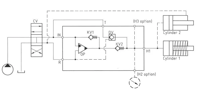
Functions Description
This system’s fundamental operation is depicted in the function diagram. Initially, oil flows through directional valve CV to the IN port, passing through check valves KV1 and KV2 to the high-pressure side H, enabling maximum flow for a swift forward function. Once pump pressure is attained on H, valves KV1, KV2, and DV close. The oscillating pump unit OP then ensures the end pressure is achieved automatically, stalling when the desired high-pressure level is reached. In the presence of a pressure drop due to consumption or leakage, the OP valve automatically activates to sustain the end pressure.
Function Diagram
Dimensions
Connection Types
| Connection | IN / R | T | H |
|---|---|---|---|
| 1 | 1/4″ BSPP | 1/4″ BSPP | M22 x 1.5 |
| 2 | 7/16-20″ UNF | 7/16-20″ UNF | M22 x 1.5 |
High-pressure Adapters
Ordering an HC7
Ordering example of an HC7-U with i = 13.0, H1 M22 x 1.5 and H2 9/16-18 UNF, DV incorporated and BSPP connections: HC7 – 13.0 – B – 12U
Attention note!
High-pressure adapter is required, please specify ordering code – see high-pressure adapter table.
High-pressure adapters will be factory mounted.
The G-model is available in 2 variants, when ordering please specify accordingly:
- Dynamic – low hysteresis: Ordering example of an HC7-U with i = 13.0 RV incorporated, H1 M22 x 1.5 and H2 9/16-18 UNF and BSPP connections: HC7 – 13.0 – G – 12U
- Fail safe – high hysteresis: The RV valve opening ratio is to be determined on individual basis. Contact our technical support. Ordering example of an HC7-U with i = 13.0 RV with opening ratio x.x incorporated, H1 M22 x 1.5 and H2 9/16-18 UNF and BSPP connections: HC7 – 13.0 – G – x.x – 12U.
Model
- HC7U

Intensification, i
- Select factor
- See flow rate table
Model Version.
- Select type
- A = without DV
- B = with DV
- G = with proportional valve
Connections.
- Select thread
- See table below
| Ordering code | IN / R | H1 | H2 | H3 |
|---|---|---|---|---|
| HC7-___-__-11U | 1/4″ BSPP | M22 x 1.5 | – | – |
| HC7-___-__-21U | 7/16-20 UNF | M22 x 1.5 | – | – |
| HC7-___-__-12U | 1/4″ BSPP | M22 x 1.5 | 9/16-18 UNF | – |
| HC7-___-__-22U | 7/16-20 UNF | M22 x 1.5 | 9/16-18 UNF | – |
| HC7-___-__-13U | 1/4″ BSPP | M22 x 1.5 | 9/16-18 UNF | 9/16-18 UNF |
| HC7-___-__-23U | 7/16-20 UNF | M22 x 1.5 | 9/16-18 UNF | 9/16-18 UNF |
Max. Tightening Torque BSPP
| IN / R | T | |
| 1/4″ BSPP | 1/4″ BSPP | |
| with steel washer | 4.0 da/Nm | 4.0 da/Nm |
| with cutting edge | 4.0 da/Nm | 4.0 da/Nm |
Max. tightening torque flange mounting
| IN / R | T | |
| 7/16-20″UNF | 9/16-18 UNF | |
| with o-ring | 2.0 da/Nm | 3.5 da/Nm |