


Product Specifications
- Automatically activated (sequence valve)
- High pressure – up to 700 bar (10,000 psi)
- Max. inlet pressure = 350 bar (5,000 psi)
- Fast fill – system flows up to 400 l/min
- Adjustable outlet pressure
- Extended service life
- Robust design
- Flexible design; several boosters/intensification factors
- Switch from by-pass to intensified flow
Functions
The function of the system is simple, but smart. The hydraulic oil is by-passed directly from the pump to the workload at maximum flow when back pressure from the workload has reached a set point close to the maximum pressure of pump.
A sequence valve opens and directs the oil to the booster, which makes the pressure rise. The shift between maximum pump pressure and high pressure happens without intervention from the user and ensures that the workload at all times will be driven at a maximum speed in relation to the required high pressure.
A relief valve is installed to control the maximum allowable pressure the system can output, allowing the booster to go for a higher end pressure producing flow at the decided pressure.
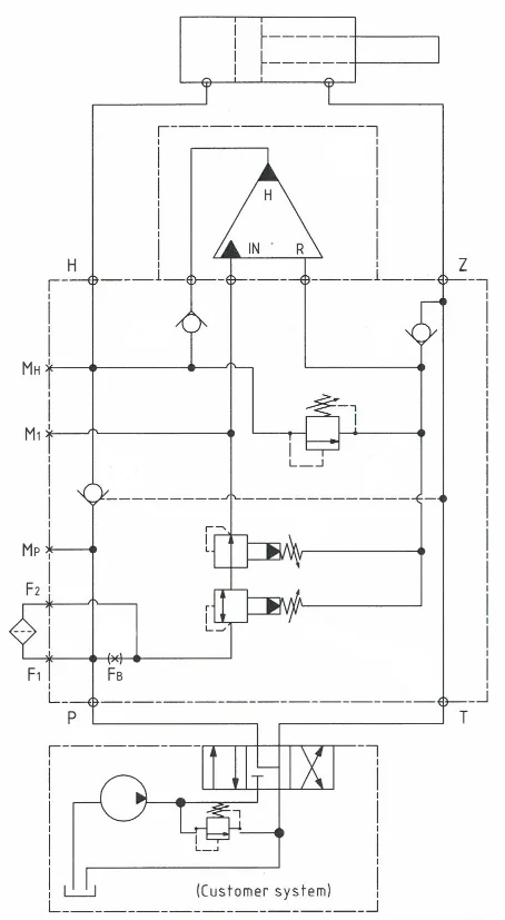
Function Diagram
Function Diagram M-HC3-013-2.0-FK100
Dimension Drawing
Dimension Drawing M-HC3-013-2.0-FK100
Connection Types
| Connection | P / T / Z / H | M (P / H / 1), F1 / F2 |
|---|---|---|
| M-HC2D-01_-1L55 | 1/2″ BSPP | 1/4″ BSPP |
| M-HC2D-01_-1L100 | 1/2″ BSPP | 1/4″ BSPP |
| M-HC3-01_-1L55 | 1/2″ BSPP | 1/4″ BSPP |
| M-HC3-01_-1L100 | 1/2″ BSPP | 1/4″ BSPP |
| M-HC6D-01_-1L100 | 1/2″ BSPP | 1/4″ BSPP |
| M-HC6D-01_-1L200 | 1 1/4″ BSPP | 1/4″ BSPP |
| M-HC6D-01_-1L400 | 1 1/4″ BSPP | 1/4″ BSPP |
Flange Mounting
Flange Mounting M-HC3-013-2.0-FK100
Ordering an M-HC-013
Ordering example of an M-HC-013 for 700 bar, connection tube BSPP with HC3 i = 2.0, static use:
M-HC3-013-FK100 mounted with HC3 – 2.0 – A – D
Guidance to calculate the intensification factor for dynamic or static use is at the bottom of this section.
Attention notes!
Valve pre-settings are required, please specify when ordering the intensifier system.
Selection of intensifier system
| Ordering code | Connection | Bypass flow | Max. pressure | Weight |
|---|---|---|---|---|
| M-HC6D-013-1K400 | Tube | 400 l/min | 500 bar | 46.5 kg |
| M-HC2D-013-1L55 | Tube | 55 l/min | 700 bar | 11.9 kg |
| M-HC3-013-1L55 | Tube | 55 l/min | 700 bar | 10.3 kg |
| M-HC2D-013-1L100 | Tube | 100 l/min | 700 bar | 12.6 kg |
| M-HC3-013-1L100 | Tube | 100 l/min | 700 bar | 10.9 kg |
| M-HC6D-013-1L100 | Tube | 100 l/min | 700 bar | 33.0 kg |
| M-HC6D-013-1L200 | Tube | 200 l/min | 700 bar | 44.0 kg |
| M-HC6D-013-1L400 | Tube | 400 l/min | 700 bar | 47.0 kg |
| M-HC2D-013-FK100 | Flange | 100 l/min | 500 bar | 10.2 kg |
| M-HC3-013-FK100 | Flange | 100 l/min | 500 bar | 8.7 kg |
| M-HC2D-013-FL100 | Flange | 100 l/min | 700 bar | 11.5 kg |
| M-HC3-013-FL100 | Flange | 100 l/min | 700 bar | 9.8 kg |
| M-HC6D-013-FL100 | Flange | 100 l/min | 700 bar | 30.0 kg |
| M-HC6D-013-FL200 | Flange | 200 l/min | 700 bar | 40.0 kg |
| M-HC6D-013-FL400 | Flange | 400 l/min | 700 bar | 43.0 kg |
Selection of intensification factor
| HC2D-_._-A-D | HC3-_._-A-D | HC6D-_._-A-D |
|---|---|---|
| 1.6 | 1.5 | 1.5 |
| 1.9 | 2.0 | 2.0 |
| 2.2 | 2.8 | 2.5 |
| 2.6 | 3.2 | 3.3 |
| 3.2 | 4.0 | 4.0 |
| 4.0 | 5.0 | 4.9 |
| 5.0 | 6.6 | 6.3 |
| 6.6 | 9.0 | 8.2 |
| 69.0 |
The intensification factor depends on available inlet and desired outlet pressure. To calculate the initial factor, use the following formular:
i = Desired high pressure / pump pressure
Desired pressure: 550 bar
Pump pressure: 207 bar
i = 550 / 207 = 2.7
For static use: Select an intensification factor higher or equal to the calculated value. In this example calculated i = 2.7, select factor i = 2.8 for an HC3 booster. The desired pressure of 550 bar is finally adjusted with the Pressure Reducing Valve (5).
For dynamic use: Select an intensification factor 40% higher than the calculated value. In this example calculated i = 550 / 207 = 2.66 + 40% = 3.7, select factor i = 4.0 for an HC3 booster. The desired pressure of 550 bar is finally adjusted with the Relief Valve (6).
Max. tightening torque
| P / T / Z | H/Z | |
| 1/2″ BSPP | 1/2″ BSPP | |
| with steel washer | 13.0 da/Nm | 13.0 da/Nm |
| with cutting edge | 13.0 da/Nm | 13.0 da/Nm |