


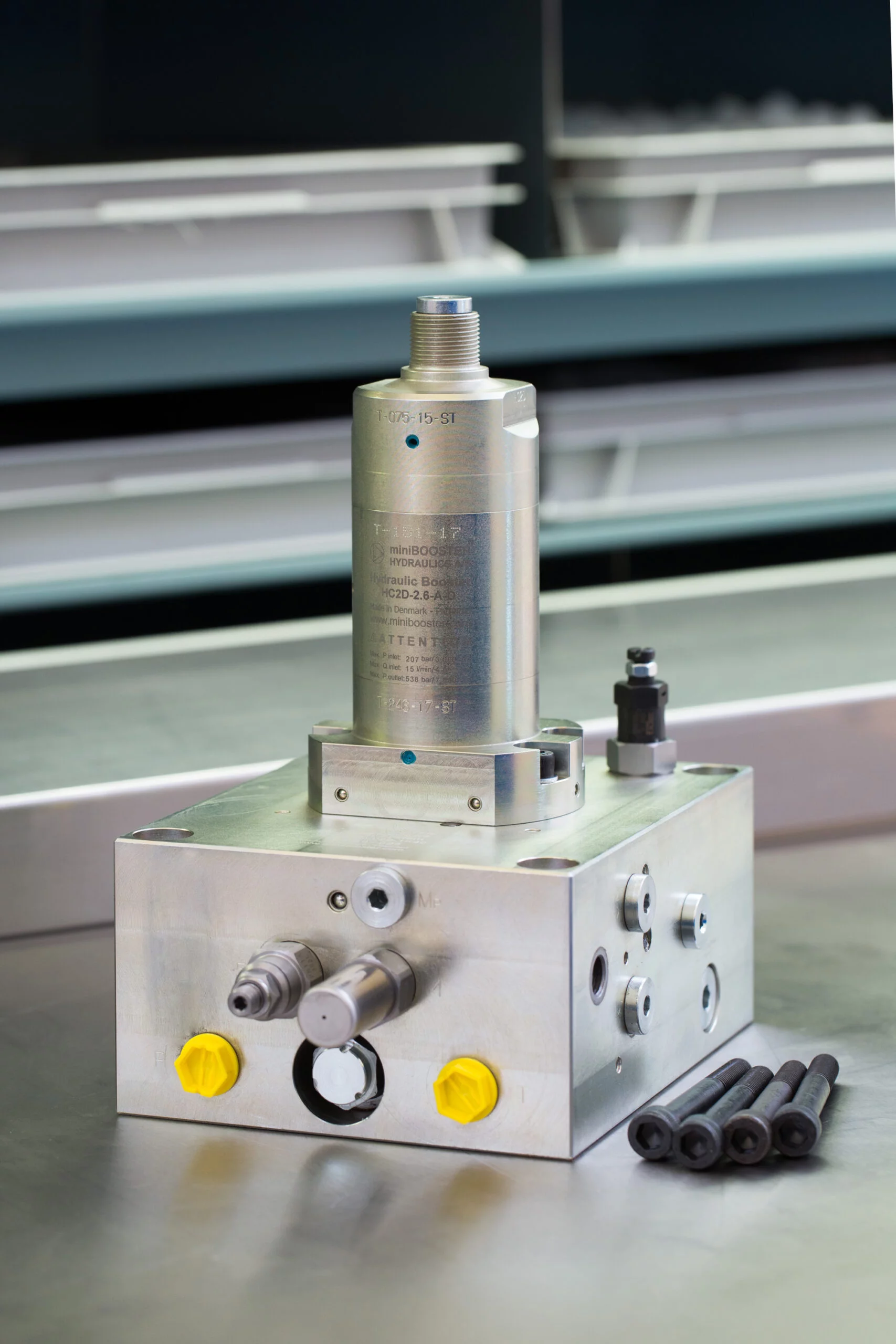

Specifications
- Automatically activated (sequence valve)
- High pressure in both directions
- High pressure – up to 500 bar (7,250 psi)
- Max. inlet pressure = 350 bar (5,000 psi)
- Fast fill – system flows up to 40 l/min
- Adjustable outlet pressure
- Extended service life
- Robust design
- Flexible design; several intensification factors
- Switch from by-pass to intensified flow
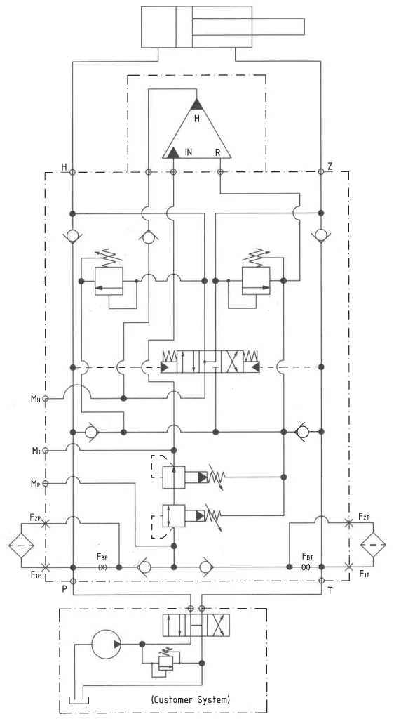
Function Description
The system autonomously directs hydraulic oil from the pump to the workload at max flow when workload back pressure nears pump max pressure. A sequence valve channels oil to a booster, increasing pressure seamlessly. A relief valve regulates maximum output pressure, optimizing performance without user intervention.
Function Diagram
Function Diagram M-HC2D-029-4.0-1K40
Dimensions Drawing
Dimension Diagram M-HC2D-029-4.0-1K40
Connection Type
| Connection | P / T / Z / H | M (P / H / 1), F1_ / F2_ |
|---|---|---|
| M-HC2D-029-1K40 | 3/8″ BSPP | 1/4″ BSPP |
Ordering an M-HC-029
Ordering example of an M-HC-029 for 500 bar, connection tube BSPP with HC2D i = 4.0, static use:
M-HC2D-029-1K40 mounted with HC2D – 1.6 – A – D
Guidance to calculate the intensification factor for dynamic or static use is at the bottom of this section.
Attention note!
Valve pre-settings are required, please specify when ordering the intensifier system.
Selection of intensifier system
| Ordering code | Connection | Bypass flow | Max. pressure | Weight |
|---|---|---|---|---|
| M-HC2D-029-1K40 | Tube | 40 l/min | 500 bar | 23.0 kg |
Selection of intensification factor
| HC2D-_._-A-D | HC3-_._-A-D |
|---|---|
| 1.6 | 1.5 |
| 1.9 | 2.0 |
| 2.2 | 2.8 |
| 2.6 | 3.2 |
| 3.2 | 4.0 |
| 4.0 | 5.0 |
| 5.0 | 6.6 |
| 6.6 | 9.0 |
| 9.0 |
The intensification factor depends on available inlet and desired outlet pressure. To calculate the initial factor, use the following formular:
i = Desired high pressure / pump pressure
Desired pressure: 500 bar
Pump pressure: 207 bar
i = 500 / 207 = 2.4
For static use: Select an intensification factor higher or equal to the calculated value. In this example calculated i = 2.4, select factor i = 2.6. The desired pressure of 500 bar is finally adjusted with the Pressure Reducing Valve (5).
For dynamic use: Select an intensification factor 40% higher than the calculated value. In this example calculated i = 500 / 207 = 2.4 + 40% = 3.4, select factor i = 4.0. The desired pressure of 500 bar is finally adjusted with the Relief Valves (6).
Max. tightening torque BSPP
| P / T / Z / H | M (P / H / 1),F1_ / F2_ | |
|---|---|---|
| 3/8″ BSPP | 1/4″ BSPP | |
| with steel washer | 6.0 da/Nm | 4.0 da/Nm |
| with cutting edge | 6.0 da/Nm | 4.0 da/Nm |
Max. tightening torque flange mounting
| Mounting bolt | ||
|---|---|---|
| M10 | 7.0 da/Nm |