


Product Specifications
- Versions: 10 different intensification factors
- PIN: 20-207 bar
- PH: 2,000 bar maximum for media > 5 cSt (mm2/s)
- PH: 1,035 bar maximum for media < 5 cSt (mm2/s)
- PRETURN: As low as possible (return pressure to tank)
- POUTLET: PH = (PIN – PRETURN) x intensification factor
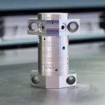
- Mounting: Flange, manifold system miniBOOSTER pattern
- Weight: 2.0 kg
Model Versions:
- A model = no dump valve
- B model = with dump valve
- G model = direct proportionally controlled
Material certificate 3.1 on request
Flow Rate
| Intensification Factor (i) | Max. Intensified Outlet Flow (l/min) | Max. Inlet Flow (l/min) |
|---|---|---|
| 4.0 | 2.0 | 14.0 |
| 5.0 | 1.6 | 14.0 |
| 6.6 | 1.3 | 13.0 |
| 7.6 | 1.1 | 13.0 |
| 9.0 | 0.9 | 13.0 |
| 10.3 | 0.8 | 12.0 |
| 13.0 | 0.6 | 12.0 |
| 16.0 | 0.5 | 12.0 |
| 20.0 | 0.3 | 12.0 |
| 25.0 | 0.2 | 12.0 |
Functions Description
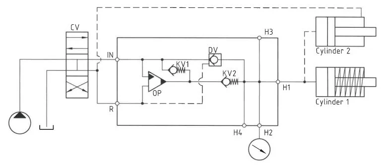
Media flows through CV to IN port, passing KV1, KV2, and DV to high-pressure side H for maximum booster flow. As pump pressure is reached, valves KV1, KV2, DV close. OP unit regulates end pressure, automatically stalling at desired pressure on H side. If pressure drops due to consumption or leakage, OP valve maintains end pressure automatically, illustrated in the function diagram for system operation.
Function Diagram
Function Diagram HC7W-20.0-A-FF
Dimensions
Dimension Diagram HC7W-20.0-A-FF
Connection Types
| Connection | IN / R | H |
|---|---|---|
| FF | Flange | Flange |
High Pressure adapters
Ordering an HC7W-FF
Ordering example of an HC7W-FF with i = 13.0, H, IN and R flanged and H2: 9/16-18 UNF and DV incorporated:
HC7W – 13.0 – B – FF2 for media < 5 cSt (mm2/s) tested in water HC7W – 13.0 – B – FF2S for media > 5 cSt (mm2/s) tested in hydraulic oil
Attention note!
High-pressure adapter is required, please specify ordering code – see high-pressure adapter table.
High-pressure adapters will be factory mounted.
The G-model is available in 2 variants, when ordering please specify accordingly:
- Dynamic – low hysteresis: Ordering example of an HC7W-FF with i = 13.0 RV incorporated, H, IN and R flanged and H2: 9/16-18 UNF : HC7W – 13.0 – G – FF2S
- Fail safe – high hysteresis: The RV valve opening ratio is to be determined on individual basis. Contact our technical support. Ordering example of an HC7W with i = 13.0 RV with opening ratio x.x incorporated, H, IN and R flanged and H2: 9/16-18 UNF: HC7W – 13.0 – G – x.x – FF2S
Model
- HC7W

Intensification,i
- Select factor
- See flow rate table
Model Version.
- Select type
- A = without DV
- B = with DV
- G = with proportional valve
Connections.
- Select thread
- FF = BSPP, media < 5 cSt
- FF = BSPP, media > 5 cSt
| Ordering Code | IN / R | H1 | H2 | H3 |
|---|---|---|---|---|
| HC7W-___-__-FF1 | Flange | Flange | – | – |
| HC7W-___-__-FF2 | Flange | Flange | 9/16-18 UNF | – |
| HC7W-___-__-FF3 | Flange | Flange | 9/16-18 UNF | 9/16-18 UNF |