


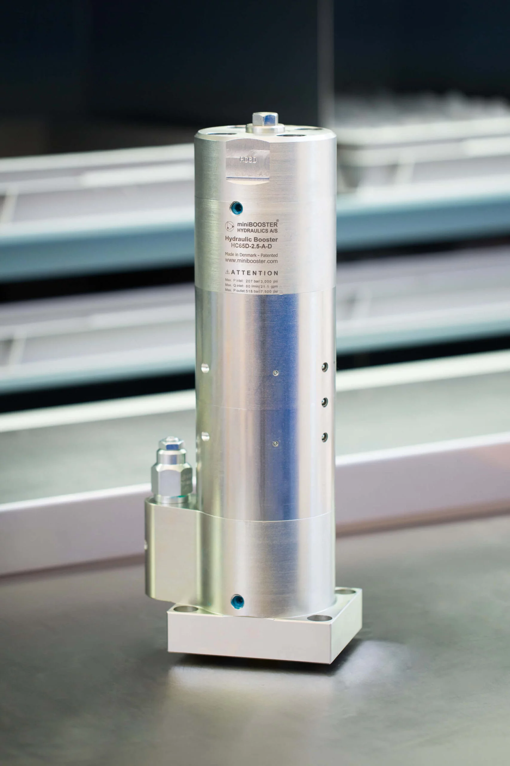

Product specification
- HC65D-D versions: 9 different intensification factors.
- PIN: 20–207 bar.
- PH: 800 bar maximum.
- PRETURN: As low as possible (return pressure to tank).
- POUTLET: PH = (PIN – PRETURN) x intensification factor.
- Mounting: Flange, Manifold system miniBOOSTER pattern.
- Weight: 21.0 kg/ 46.2 lbs.
Model versions
- A model = no dump valve.
- B model = with dump valve.
Material certificate 6.3 on request
Flow Rates
| Intensification Factor i | Max.Intensified Outlet flow i/min | Max. Inlet flow i/min |
|---|---|---|
| 1.2 | 65.0 | 80.0 |
| 1.5 | 53.0 | 80.0 |
| 2.0 | 40.0 | 80.0 |
| 2.5 | 34.0 | 80.0 |
| 3.3 | 25.6 | 80.0 |
| 4.0 | 21.2 | 80.0 |
| 4.9 | 17.2 | 80.0 |
| 6.3 | 13.4 | 80.0 |
| 8.2 | 10.4 | 80.0 |
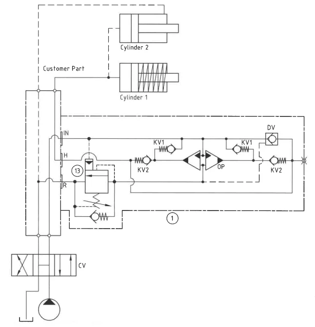
Function description
The basic operation is illustrated in the function diagram. Oil is fed through the directional valve CV to the IN port, flowing freely through the check valves 2x KV1, 2x KV2 and DV to the high-pressure side H. In this condition maximum flow through the booster is achieved, giving a fast-forward function. When pump pressure is reached on the high-pressure side H, valves KV1, KV2 and DV will close. The end pressure will be achieved by the oscillating pump units OP1 and OP2 by turns. The unit will automatically stall when end pressure on high-pressure side H is reached. If a pressure drop on the high-pressure side exists due to consumption or leakage, the OP1 and OP2 units will automatically operate to maintain the end pressure. It is possible to change the high-pressure connection H to the opposite end of the booster.
Function diagram
Function diagram HC65D-6.3-A-D
Dimension
Dimension drawing HC65D-6.3-A-D
Ordering an HC65D-D
Ordering example of a HC65D-D with i = 6.3, DV incorporated: HC65D – 6.3 – A – D
Attention note!
Valve pre-setting is required, please specify when ordering the intensifier.
Model
- HC65D

Intensification,
- Select factor
- See flow rate table
Model Version.
- Select type
- A = without DV
- B = with DV
Connections
- D