


Product specification
- HC21 versions: 15 different intensification factors.
- PIN: 20–207 bar.
- PH: 800 bar maximum.
- PRETURN: As low as possible (return pressure to tank).
- POUTLET: PH = (PIN – PRETURN) x intensification factor.
- Mounting: Inline tube.
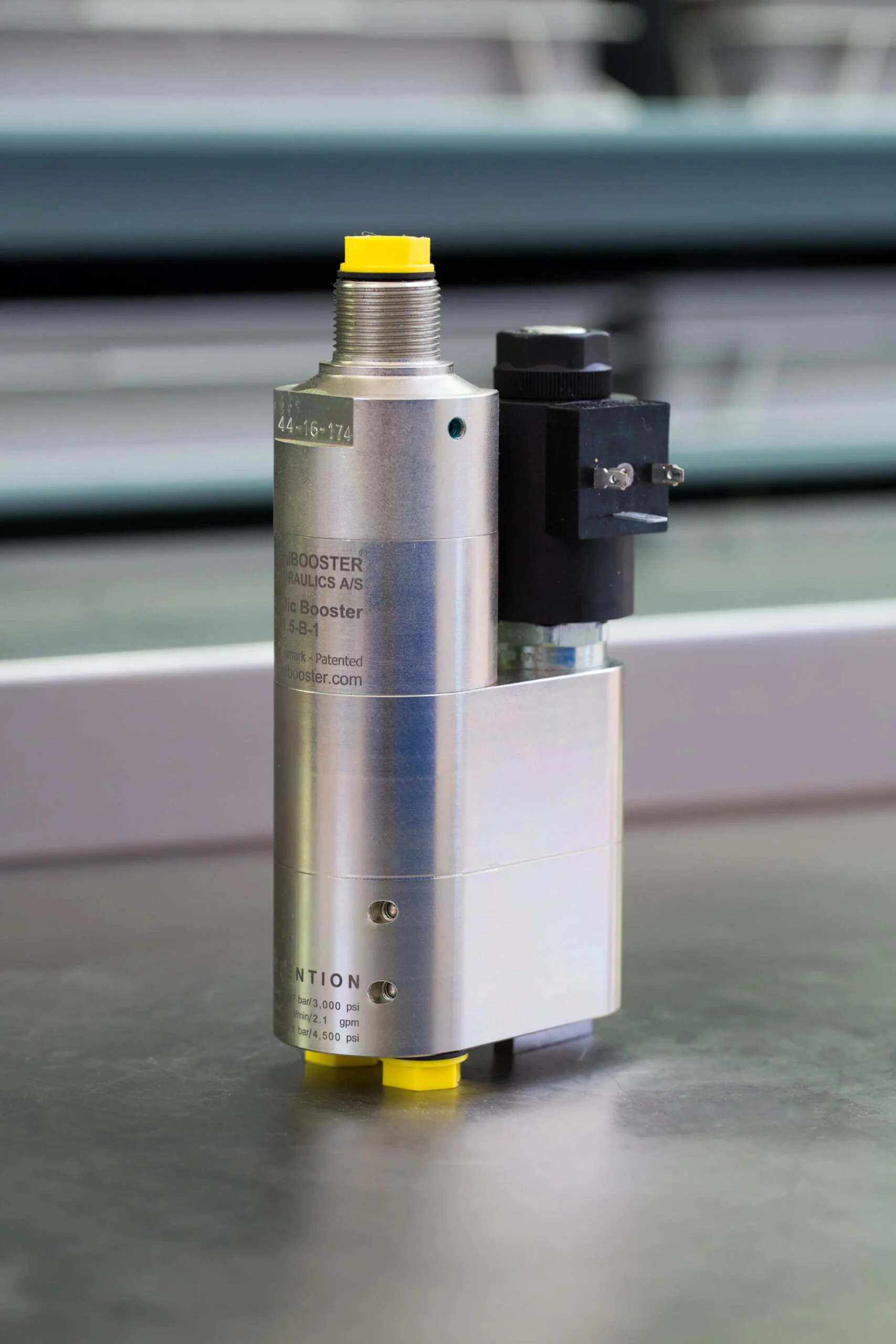
- Weight: 3.2 kg/ 7.0 lbs.
Model versions
- B model = with dump valve.
Material certificate 1.5 on request
Flow Rates
| Intensification Factor i | Max.Intensified Outlet flow i/min | Max. Inlet flow i/min |
|---|---|---|
| 1.2 | 3.5 | 8.0 |
| 1.5 | 4.2 | 12.0 |
| 2.0 | 3.2 | 12.0 |
| 2.2 | 2.9 | 12.0 |
| 2.5 | 2.7 | 13.0 |
| 2.8 | 2.5 | 13.0 |
| 3.2 | 2.5 | 15.0 |
| 4.0 | 2.0 | 14.0 |
| 5.0 | 1.6 | 14.0 |
| 6.6 | 1.3 | 13.0 |
| 9.0 | 0.9 | 13.0 |
| 13.0 | 0.6 | 12.0 |
| 16.0 | 0.5 | 12.0 |
| 20.0 | 0.3 | 12.0 |
| 25.0 | 0.2 | 12.0 |
Function description
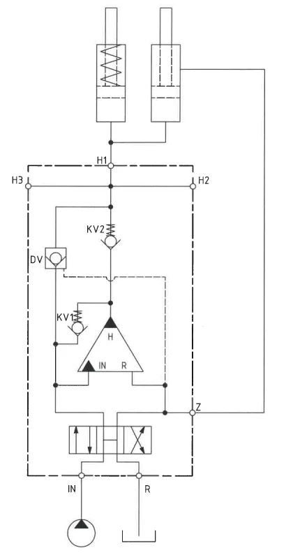
The basic operation is illustrated in the function diagram. When the DCV valve (pos. 3) is activated to parallel position, oil is fed from the pump to the IN port, flowing freely through the internal check valves to the high-pressure side H. When pump pressure is reached on the high-pressure side H, the internal check valves will close. The end pressure will be built up by the oscillating pump unit OP. The unit will automatically stall when end pressure on the high-pressure side H is reached. If the pressure drops on the high-pressure side, due to consumption or leakage, the OP valve will automatically oscillate to maintain the end pressure. When the job is done and the pressure has to be relieved again, the DCV valve has to be set in cross position. The pump pressure will pressurise the Z port, and the built-in valve DV is activated and thereby relieves the high-pressure side, and oil returns to the tank.
Function diagram HC21 with DCV type “H”
Function-Diagram HC21-1.5-B-1-12
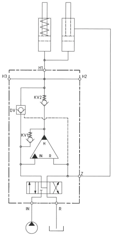
Function diagram HC21 with DCV type “h”
Function-Diagram HC21-1.5-B-1-12
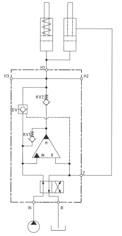
Function diagram HC21 with DCV type “4/2”
Function-Diagram HC21-1.5-B-1-12
Dimensions with solenoid operated valve
Dimension drawing HC21-1.5-B-1-12
Dimensions with manually operated valve
Dimension drawing HC21-1.5-B-1-12
Dimensions with solenoid operated valve + side ports H2/H3
Dimension drawing HC21-1.5-B-1-12
Dimensions with manually operated valve + side ports H2/H3
Dimension drawing HC21-1.5-B-1-12
Connection Types
| Connection | IN/R | H1 | H2 | H3 |
|---|---|---|---|---|
| 1 | 1/4″ BSPP | 1/4″ BSPP | – | – |
| 12 | 1/4″ BSPP | 1/4″ BSPP | 1/4″ BSPP | – |
| 13 | 1/4″ BSPP | 1/4″ BSPP | 1/4″ BSPP | 1/4″ BSPP |
Ordering an HC21
Ordering example of an HC21 with i = 1.5 DV incorporated, BSPP connections, H2 side port and manually operated directional control valve type H:
HC21 – 1.5 – B – 1 – 12
Attention note!
HC21 is as standard mounted with 12VDC coil. Other voltage available on request.
Model
- HC21

Intensification,i
- Select factor
- See flow rate table
Model Version.
- Select type
- B = with DV
Connections.
- See table above
- 1
- 12
- 13
Directional control valve.
- Select type
- 01 = Manual H
- 02 = Manual h
- 09 = Manual 4/2
- 11 = Solenoid H
- 12 = Solenoid h
- 19 = Solenoid 4/2