


Product Specifications
- HC8 versions: 10 different intensification factors
- PIN: 20-207 bar
- PH: 2,000 bar maximum
- PRETURN: As low as possible (return pressure to tank)
- POUTLET: PH = (PIN – PRETURN) x intensification factor
- Mounting: Inline tube
- Weight: 4.5 kg
Model Versions:
- A model = no dump valve
- B model = with dump valve
- G model = direct proportionally controlled
Material certificate 3.1 on request
Flow Rate
| Intensification factor | Max. intensified outlet flow (l/min) | Max. inlet flow (l/min) |
|---|---|---|
| 4.0 | 2.0 | 14.0 |
| 5.0 | 1.6 | 14.0 |
| 6.6 | 1.3 | 13.0 |
| 7.6 | 1.1 | 13.0 |
| 9.0 | 0.9 | 13.0 |
| 10.3 | 0.8 | 12.0 |
| 13.0 | 0.6 | 12.0 |
| 16.0 | 0.5 | 12.0 |
| 20.0 | 0.3 | 12.0 |
| 25.0 | 0.2 | 12.0 |
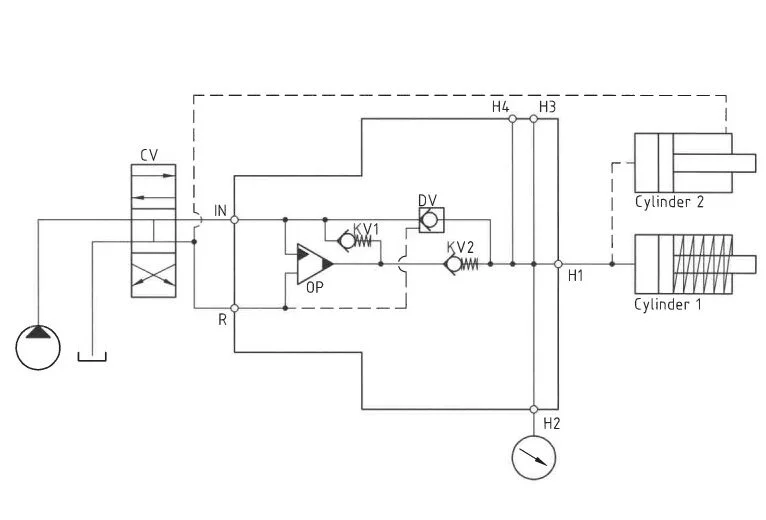
Functions Desctiption
The system operates as follows: Oil is directed through the directional valve (CV) to the IN port, where it flows freely through check valves (KV1, KV2, and DV) to the high-pressure side (H), maximizing booster flow for fast-forward functionality. Once pump pressure is attained on the high-pressure side, valves KV1, KV2, and DV close. The oscillating pump unit (OP) then achieves the desired end pressure, automatically stalling upon reaching the target pressure. If pressure drops occur due to consumption or leakage on the high-pressure side, the OP valve automatically adjusts to maintain the end pressure.
Function Diagram
Dimensions
Connection Types
| Connection | IN / R |
|---|---|
| 1 | 1/4″ BSPP |
| 2 | 7/16-20″ UNF |
High-pressure Adapters
Ordering an HC8
Ordering example of an HC8 with i = 13.0, H1 M22 x 1.5 and H2 9/16-18 UNF, DV incorporated and BSPP connections: HC8 – 13.0 – B – 12U
Ordering example of an HC8 with i = 13.0, DV incorporated and BSPP connections, mounted with high-pressure plate with HP-connection 1/4″ BSPP, PG-connection 9/16-18 UNF:
HC8 – 13.0 – B – 1 with 8-285
Attention note!
High-pressure plate is required, please specify ordering code – see high-pressure plate table.
High-pressure plate will be factory mounted.
The G-model is available in 2 variants, when ordering please specify accordingly:
- Dynamic – low hysteresis: Ordering example of an HC8 with i = 13.0 RV incorporated and BSPP connections: HC8 – 13.0 – G – 1
- Fail safe – high hysteresis: The RV valve opening ratio is to be determined on individual basis. Contact our technical support. Ordering example of an HC8 with i = 13.0 RV with opening ratio x.x incorporated and BSPP connections: HC8 – 13.0 – G – x.x – 1.
Model
- HC8

Intensification,i
- Select factor
- See flow rate table
Model Version.
- Select type
- A = without DV
- B = with DV
- G = with proportional valve
Connections.
- Your selection
- 1 = BSPP
- 2 = UNF
Max. Tightening Torque BSPP
| IN / R | |
| 1/4″ BSPP | |
| with steel washer | 4.0 da/Nm |
| with cutting edge | 4.0 da/Nm |
Max. Tightening torque UNF
| IN / R | |
|---|---|
| 7/16-20″ UNF | |
| with o-ring | 2.0 da/Nm |