


Product Specifications
- Versions: 2 different intensification factors
- PIN: 20-207 bar
- PH: 1,380 bar maximum for media > 5 cSt (mm2/s)
- PH: 1,035 bar maximum for media < 5 cSt (mm2/s)
- PRETURN: As low as possible (return pressure to tank)
- POUTLET: PH = (PIN – PRETURN) x intensification factor
- Mounting: Inline tube
- Weight: 5.4 kg
Model Versions:
- A model = no dump valve
- B model = with dump valve
- G model = direct proportionally controlled
Material certificate 3.1 on request
Flow Rate
| Intensification Factor (i) | Max. Intensified Outlet Flow (l/min) | Max. Inlet Flow (l/min) |
|---|---|---|
| 4.0 | 2.0 | 14.0 |
| 6.3 | 1.4 | 13.0 |
Functions Description
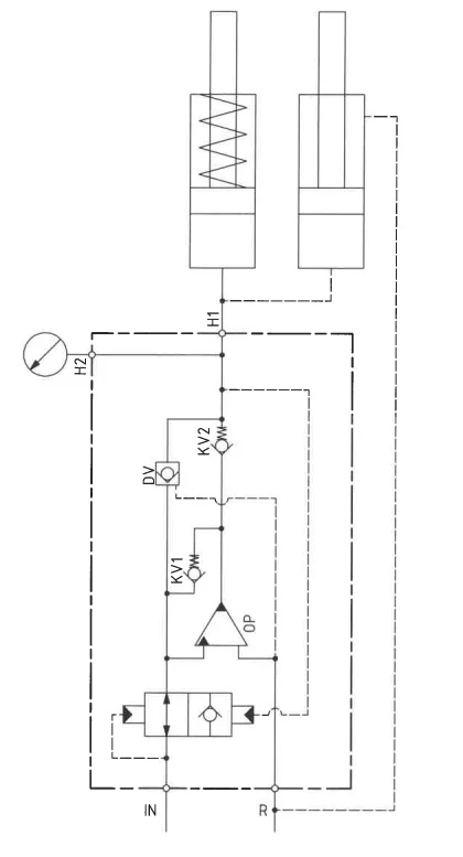
The system’s basic operation is depicted in a function diagram. Oil is directed through the directional valve CV to the IN port, flowing through the low leakage valve, internal valves KV1, KV2, and DV to the high-pressure side H, achieving maximum booster flow. As pump pressure is attained on the H side, valves KV1, KV2, and DV close. The oscillating pump unit OP regulates end pressure, automatically stalling when reached. The low leakage valve minimizes leakage by cutting off inlet flow to the booster. If pressure drops occur, it opens to maintain end pressure.
Function Diagram A- and B- Model
Dimensions
Dimension Diagram HC78-4.0-A-W
Connection Types
| Connection | IN / R | H |
|---|---|---|
| 1 | 1/4″ BSPP | M22 x 1.5 |
High Pressure adapters
Ordering an HC78W
Ordering example of an HC78W with i = 4.0, H1 M22 x 1.5 and H2 9/16-18 UNF, DV incorporated and BSPP connections:
HC78W – 4.0 – B – 12 for media < 5 cSt (mm2/s) tested in water HC78W – 4.0 – B – 12S for media > 5 cSt (mm2/s) tested in hydraulic oil
Attention note!
High-pressure adapter is required, please specify ordering code – see high-pressure adapter table.
High-pressure adapters will be factory mounted.
The G-model is available in 2 variants, when ordering please specify accordingly:
- Dynamic – low hysteresis: Ordering example of an HC78W with i = 4.0 RV incorporated, H1 M22 x 1.5 and H2 9/16-18 UNF and BSPP connections: HC78W – 4.0 – G – 12S
- Fail safe – high hysteresis: The RV valve opening ratio is to be determined on individual basis. Contact our technical support. Ordering example of an HC78W with i = 4.0 RV with opening ratio x.x incorporated, H1 M22 x 1.5 and H2 9/16-18 UNF and BSPP connections: HC78W – 4.0 – G – x.x – 12S
Model
- HC78W

Intensification,i
- Select factor
- See flow rate table
Model Version.
- Select type
- A = without DV
- B = with DV
- G = with proportional valve
Connections.
- Select thread
- 1_ = BSPP, media < 5 cSt
- 1_S = BSPP, media > 5 cSt
| Ordering Code | IN / R | H1 | H2 | H3 |
|---|---|---|---|---|
| HC78W-___-__-11 | 1/4″ BSPP | M22 x 1.5 | – | – |
| HC78W-___-__-12 | 1/4″ BSPP | M22 x 1.5 | 9/16-18 UNF | – |
| HC78W-___-__-13 | 1/4″ BSPP | M22 x 1.5 | 9/16-18 UNF | 9/16-18 UNF |
Max. tightening torque BSPP
| IN / R | |
| 1/4″ BSPP | |
| with stainless steel washer | 4.0 da/Nm |