


Product Specifications
- HC7-F versions: 10 different intensification factors
- PIN: 20 – 207 bar
- PH: 2,000 bar maximum
- PRETURN: As low as possible (return pressure to tank)
- POUTLET: PH = (PIN – PRETURN) x intensification factor
- Mounting: Flange, manifold system miniBOOSTER pattern
- Weight: 1.7 kg
Model Versions:
- A model = no dump valve
- B model = with dump valve
- B model = direct proportionally controlled
Material certificate 3.1 on request
Flow Rate
| Intensification Factor | Max. Intensified Outlet Flow (l/min) | Max. Inlet Flow (l/min) |
|---|---|---|
| 4.0 | 2.0 | 14.0 |
| 5.0 | 1.6 | 14.0 |
| 6.6 | 1.3 | 13.0 |
| 7.6 | 1.1 | 13.0 |
| 9.0 | 0.9 | 13.0 |
| 10.3 | 0.8 | 12.0 |
| 13.0 | 0.6 | 12.0 |
| 16.0 | 0.5 | 12.0 |
| 20.0 | 0.3 | 12.0 |
| 25.0 | 0.2 | 12.0 |
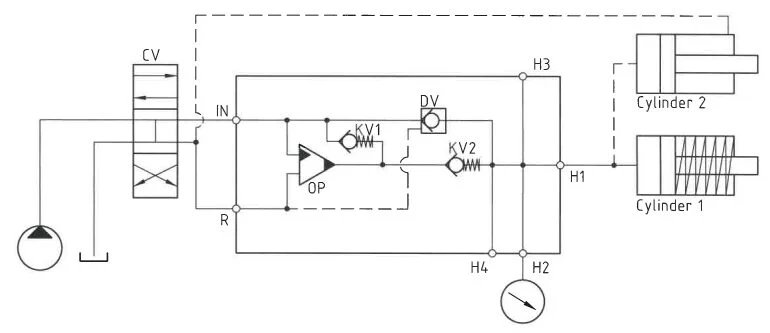
Functions Desctiption
The system operates as follows: Oil is directed through the directional valve CV to the IN port, passing through check valves KV1, KV2, and DV to the high-pressure side H, allowing for maximum flow and a fast-forward function. Once the pump pressure is attained on the high-pressure side H, valves KV1, KV2, and DV close. The oscillating pump unit OP then maintains the end pressure automatically, stalling when the desired pressure is reached. In the presence of a pressure drop due to consumption or leakage on the high-pressure side, the OP valve ensures automatic operation to sustain the end pressure.
Function Diagram
Dimensions
Dimension drawing HC7-16.0-B-F
Connection Types
| Connection | IN / R | H |
|---|---|---|
| F | Flange | M22 x 1.5 |
High-pressure Adapters
Ordering an HC7
Ordering example of an HC7-F with i = 13.0, H1 M22 x 1.5 and H2 9/16-18 UNF, DV incorporated and BSPP connections: HC7 – 13.0 – B – F2
Attention note!
High-pressure adapter is required, please specify ordering code – see high-pressure adapter table.
High-pressure adapters will be factory mounted.
The G-model is available in 2 variants, when ordering please specify accordingly:
- Dynamic – low hysteresis: Ordering example of an HC7-F with i = 13.0 RV incorporated, H1 M22 x 1.5 and H2 9/16-18 UNF and BSPP connections: HC7 – 13.0 – G – F2
- Fail safe – high hysteresis: The RV valve opening ratio is to be determined on individual basis. Contact our technical support. Ordering example of an HC7-F with i = 13.0 RV with opening ratio x.x incorporated, H1 M22 x 1.5 and H2 9/16-18 UNF and BSPP connections: HC7 – 13.0 – G – x.x – F2.
Model
- HC7F

Intensification,i
- Select factor
- See flow rate table
Model Version.
- Select type
- A = without DV
- B = with DV
- G = with proportional valve
Connections.
- See table below
| Ordering Code | IN / R | H1 | H2 | H3 |
|---|---|---|---|---|
| HC7-___-__-F1 | Flange | M22 x 1.5 | – | – |
| HC7-___-__-F2 | Flange | M22 x 1.5 | 9/16-18 UNF | – |
| HC7-___-__-F3 | Flange | M22 x 1.5 | 9/16-18 UNF | 9/16-18 UNF |