


Product Specifications
- HC7 versions: 10 different intensification factors
- PIN: 20 – 207 bar
- PH: 2,000 bar maximum
- PRETURN: As low as possible (return pressure to tank)
- POUTLET: PH = (PIN – PRETURN) x intensification factor
- Mounting: Inline tube
- Weight: 1.5 kg
Model Versions:
- A model = no dump valve
- B model = with dump valve
- B model = direct proportionally controlled
Material certificate 3.1 on request
Flow Rate
| i (Intensification factor) | Max. intensified outlet flow (l/min) | Max. inlet flow (l/min) |
|---|---|---|
| 4.0 | 2.0 | 14.0 |
| 5.0 | 1.6 | 14.0 |
| 6.6 | 1.3 | 13.0 |
| 7.6 | 1.1 | 13.0 |
| 9.0 | 0.9 | 13.0 |
| 10.3 | 0.8 | 12.0 |
| 13.0 | 0.6 | 12.0 |
| 16.0 | 0.5 | 12.0 |
| 20.0 | 0.3 | 12.0 |
| 25.0 | 0.2 | 12.0 |
Functions Desctiption
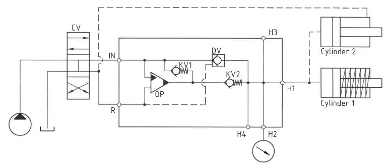
This system utilizes a directional valve (CV) to regulate the flow of oil, allowing it to pass through check valves (KV1, KV2, and DV) to reach the high-pressure side (H). Initially, maximum flow through the booster is attained for rapid forward motion. Once pump pressure is attained on the high-pressure side, the valves (KV1, KV2, and DV) close. The oscillating pump unit (OP) then maintains the end pressure automatically, stalling when the desired pressure is reached. Should there be a pressure drop due to consumption or leakage, the OP valve adjusts accordingly to uphold the end pressure.
Function Diagram
Dimensions
Connection Types
| Connection | IN / R | H |
|---|---|---|
| 1 | 1/4″ BSPP | M22 x 1.5 |
| 2 | 7/16-20″ UNF | M22 x 1.5 |
High-pressure adapters
Ordering an HC7
Ordering example of an HC7 with i = 13.0, H1 M22 x 1.5 and H2 9/16-18 UNF, DV incorporated and BSPP connections: HC7 – 13.0 – B – 12
Attention note!
High-pressure adapter is required, please specify ordering code – see high-pressure adapter table.
High-pressure adapters will be factory mounted.
The G-model is available in 2 variants, when ordering please specify accordingly:
- Dynamic – low hysteresis: Ordering example of an HC7 with i = 13.0 RV incorporated, H1 M22 x 1.5 and H2 9/16-18 UNF and BSPP connections: HC7 – 13.0 – G – 12.
- Fail safe – high hysteresis: The RV valve opening ratio is to be determined on individual basis. Contact our technical support. Ordering example of an HC7 with i = 13.0 RV with opening ratio x.x incorporated, H1 M22 x 1.5 and H2 9/16-18 UNF and BSPP connections: HC7 – 13.0 – G – x.x – 12 .
Model
- HC7

Intensification,i
- Select factor
- See flow rate table
Model Version.
- Select type
- A = without DV
- B = with DV
- G = with proportional valve
Connections.
- Select thread
- See table below
| Ordering code | IN / R | H1 | H2 | H3 | H4 |
|---|---|---|---|---|---|
| HC7-___-__-11 | 1/4″ BSPP | M22 x 1.5 | – | – | – |
| HC7-___-__-21 | 7/16-20 UNF | M22 x 1.5 | – | – | – |
| HC7-___-__-12 | 1/4″ BSPP | M22 x 1.5 | 9/16-18 UNF | – | – |
| HC7-___-__-22 | 7/16-20 UNF | M22 x 1.5 | 9/16-18 UNF | – | – |
| HC7-___-__-13 | 1/4″ BSPP | M22 x 1.5 | 9/16-18 UNF | 9/16-18 UNF | – |
| HC7-___-__-23 | 7/16-20 UNF | M22 x 1.5 | 9/16-18 UNF | 9/16-18 UNF | – |
| HC7-___-__-14 | 1/4″ BSPP | M22 x 1.5 | 9/16-18 UNF | 9/16-18 UNF | 9/16-18 UNF |
| HC7-___-__-24 | 7/16-20 UNF | M22 x 1.5 | 9/16-18 UNF | 9/16-18 UNF | 9/16-18 UNF |
Max. Tightening Torque BSPP
| IN / R | |
| 1/4″ BSPP | |
| with steel washer | 4.0 da/Nm |
| with cutting edge | 4.0 da/Nm |
Max. tightening torque flange mounting
| 7/16-20″UNF | ||
| With O-ring | 2.0 da/Nm |