


Product specification
- HC425 versions: 11 different intensification factors.
- PIN: 20 – 207 bar.
- PH: 800 bar maximum.
- PRETURN: As low as possible (return pressure to tank).
- POUTLET: PH = (PIN – PRETURN) x intensification factor.
- Mounting: Inline tube.
- Weight: 5.5 kg/ 12.1 lbs.
Model versions
- A model = no dump valve.
- B model = with dump valve.
Material certificate 1.8 on request
Flow Rates
| Intensification Factor i | Max.Intensified Outlet flow i/min | Max. Inlet flow i/min |
|---|---|---|
| 1.3 | 16.3 | 40.0 |
| 1.5 | 14.1 | 40.0 |
| 1.8 | 11.8 | 40.0 |
| 2.1 | 10.1 | 40.0 |
| 2.6 | 8.1 | 40.0 |
| 2.8 | 7.6 | 40.0 |
| 3.2 | 6.5 | 40.0 |
| 4.3 | 5.0 | 40.0 |
| 5.1 | 4.1 | 40.0 |
| 6.3 | 3.4 | 40.0 |
| 9.8 | 2.2 | 40.0 |
Function description
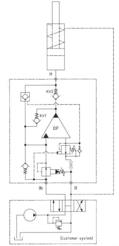
The basic operation is illustrated in the function diagram. Oil is fed through the directional valve (in the customer system) to the IN port, flowing freely through the PRV (pos. 5) and the internal check valves to the high-pressure side H. In this condition maximum flow through the booster is achieved giving a fast-forward function. When pump pressure is reached on the high-pressure side H, the internal check valves will close. The end pressure will be achieved by the oscillating pump unit OP. The unit will automatically stall when end pressure on the high-pressure side H is reached. If a pressure drop on the high-pressure side exists due to consumption or leakage, the OP valve will automatically operate to maintain the end pressure.
Function diagram
Function diagram HC425-1.8-A-1
Dimension
Dimension drawing HC425-1.8-A-1
Connection Types
| Connection | IN/R | H |
|---|---|---|
| 1 | 1/2″ BSPP | 1/2″ BSPP |
Ordering an HC425
Ordering example of an HC425 with i = 1.8, DV incorporated and BSPP connections: HC425 – 1.8 – A – 1
Attention note!
Valve pre-settings are required, please specify when ordering the intensifier.
Model
- HC425

Intensification,
- Select factor
- See flow rate table
Model Version.
- Select type
- A = without DV
- B = with DV
Connections
- Select thread
- 1 = BSPP
Max. tightening torque BSPP
| IN / R | H | |
| 1/2″ BSPP | 1/2″ BSPP | |
| with steel washer | 13.0 da/Nm | 13.0 da/Nm |
| with cutting edge | 13.0 da/Nm | 13.0 da/Nm |