


Product specification
- HC4 – H – NG versions: 11 different intensification factors.
- PIN: 20 – 207 bar.
- PH: 500 bar maximum.
- PRETURN: As low as possible (return pressure to tank).
- POUTLET: PH = (PIN – PRETURN) x intensification factor.
- Mounting: NG6 (D03) or NG10 (D05) stacking manifold system.
- Weight: NG6: 6.0 kg/ 13.2 lbs / NG10: 6.2 kg/ 13.6 lbs.
Model versions
- A model = no dump valve.
- B model = with dump valve.
- G model = direct proportionally controlled.
Material certificate 9.8 on request
Flow Rates
| Intensification Factor i | Max.Intensified Outlet flow i/min | Max. Inlet flow i/min |
|---|---|---|
| 1.3 | 16.3 | 40.0 |
| 1.5 | 14.1 | 40.0 |
| 1.8 | 11.8 | 40.0 |
| 2.1 | 10.1 | 40.0 |
| 2.6 | 8.1 | 40.0 |
| 2.8 | 7.6 | 40.0 |
| 3.2 | 6.5 | 40.0 |
| 4.3 | 5.0 | 40.0 |
| 5.1 | 4.1 | 40.0 |
| 6.3 | 3.4 | 40.0 |
| 9.8 | 2.2 | 40.0 |
Function description
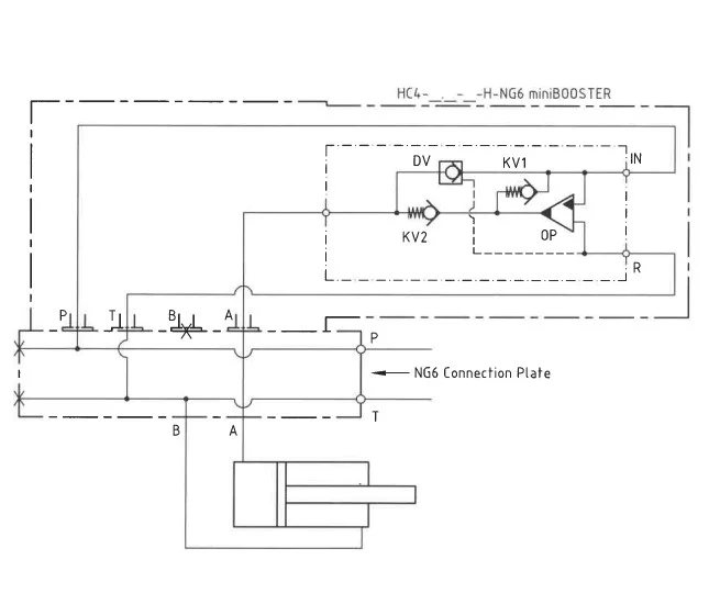
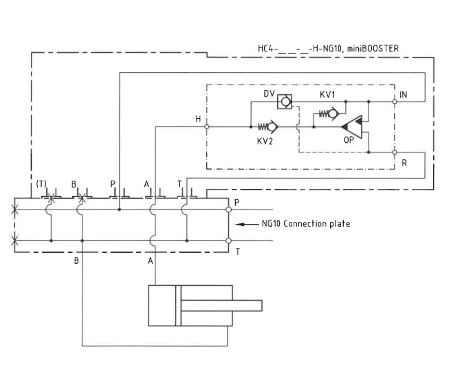
The basic operation is illustrated in the function diagram. The oil is fed through the connecting plate and the filter to the IN port of the HC4-H-NG flowing freely through check valves KV1, KV2 and DV to the high- pressure side H. From the high-pressure side H oil is fed to port A on the connecting plate. In this condition maximum flow through the booster is achieved giving a fast-forward function. When pump pressure is reached on the high-pressure side H, valves KV1, KV2 and DV will close. The end pressure will be achieved by the oscillating pump unit OP. The unit will automatically stall when end pressure on the high-pressure side is reached. If a pressure drop on the high-pressure side exists due to consumption or leakage, the OP valve will automatically operate to maintain the end pressure.
Function diagram HC4-9.8-B-H-NG6
Function-Diagram HC4-9.8-B-H-NG6
Function diagram HC4-9.8-B-H-NG10
Function-Diagram HC4-9.8-B-H-NG10
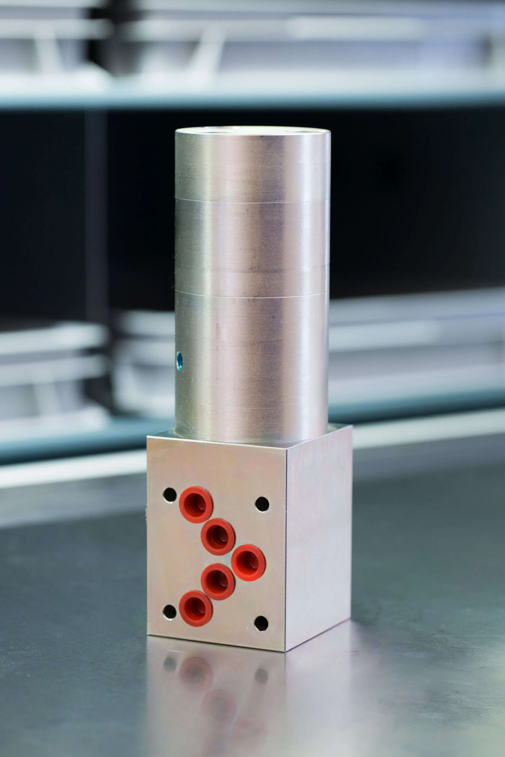
Dimensions HC4-9.8-B-H-NG6
Dimension drawing HC4-9.8-B-H-NG6
Dimensions HC4-9.8-B-H-NG10
Dimension drawingHC4-9.8-B-H-NG10
Ordering an HC4-H-NG
Ordering example of an HC4 – H – NG with i = 9.8, DV incorporated and NG6 (D03) manifold: HC4 – 9.8 – B – H – NG6
Attention note!
- Dynamic – low hysteresis: Ordering example of an HC4-H-NG with i = 9.8 RV incorporated and NG6 (D03) manifold: HC4 – 9.8 – B – H – NG6.
- Fail safe – high hysteresis: The RV valve opening ratio is to be determined on individual basis. Contact our technical support.
Model
- HC4

Intensification,i
- Select factor
- See flow rate table
Model Version.
- Select type
- A = without DV
- B = with DV
- G = with proportional valve
Connections.
- Select manifold
- H-NG6
- H-HG10